

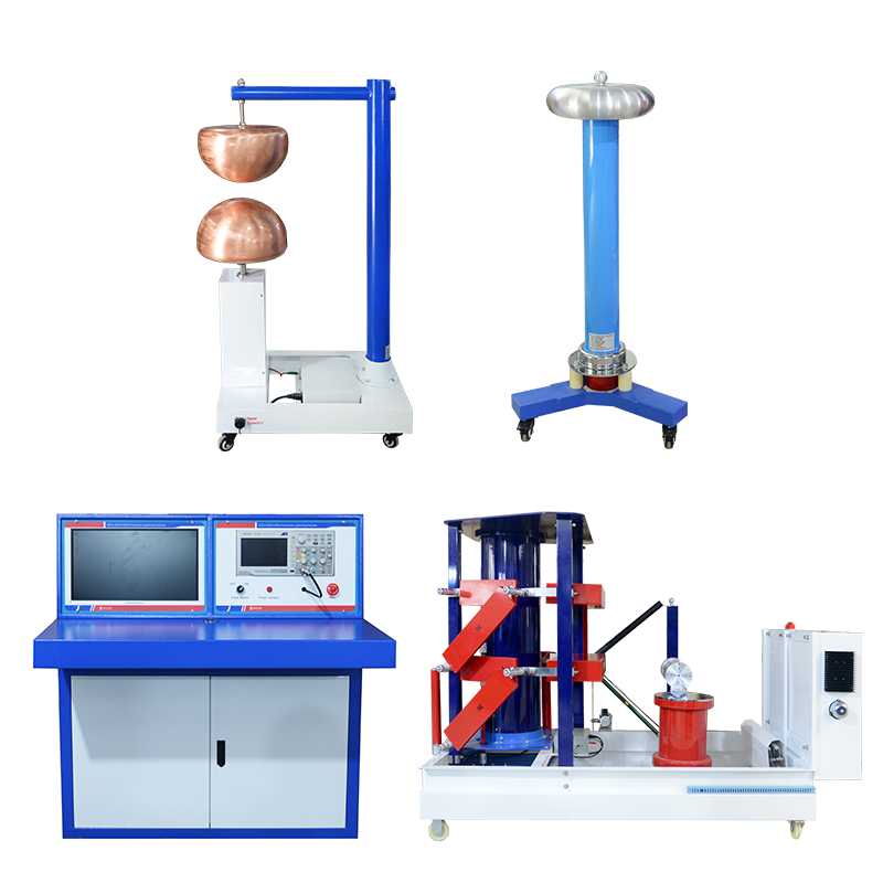
Lightning Impulse Voltage Generator
Lightning Impulse Voltage Generator
DMC chopped wave device
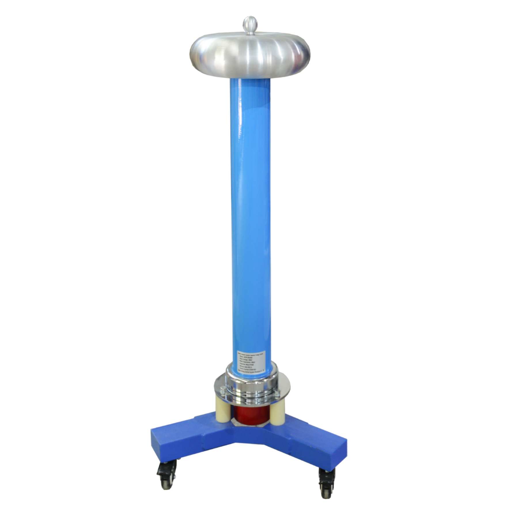
DCR low damping voltage divider
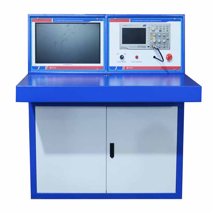
DCJ-DY impulse voltage generator control system
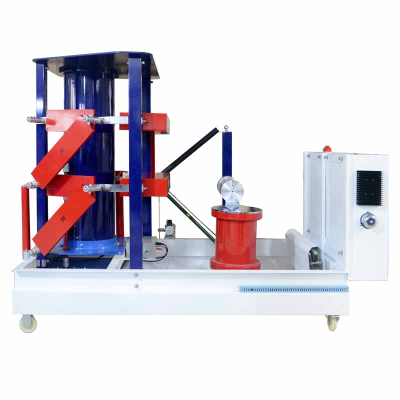
DCJ-DY impulse voltage generator main body
Application for lightning impulse voltage full-wave, lightning impulse voltage chopped-wave (optional) and impulse voltage switching surge (optional) test of electrical equipment and other test products, to check insulation performance.
Features:
◆Stable waveform,the control and measurement system used is a mature product in China. The core component is the FX system programmable controller of Mitsubishi Corporation of Japan. Almost all control functions are realized by software programming. Therefore, the system has a simple structure, few peripheral circuit boards, high reliability.
◆Full automatic control,the operation interface of the control and measurement system adopted fully considers the customary characteristics of high-voltage tests, which is simple and clear, and is convenient for testers to operate. The system has designed a special program operation interface, which greatly simplifies the operation of the test personnel and can effectively prevent human errors.
◆Long service life,this set of lightning impulse voltage generator test system adopts advanced technology, good craftsmanship and high-quality raw materials, which can ensure long-term use and operation life of more than 20 years. The usual running costs are also low.
◆The main structure adopts the current compact generator, which has the characteristics of small inherent inductance and convenient wave adjustment.
◆Integrated overall design of measurement and control structure,adopt optical fiber control transmission system realizes the optical fiber connection between the control measurement equipment and the high-voltage main equipment, effectively solves the harm to the measurement and control system caused by the elevated ground potential encountered in the high-voltage test, and eliminates the electromagnetic interference caused by the control leads. Highly improves the reliability of the system.
Specification:
Standard Voltage | Impulse Capacitance(µF) | Classes Capacitance(µF) | Impulse Energy(kJ) | Classes Voltage(kV) | Class | Weight(kg) | |||||
±300~±900 | 0.133~0.111 | 0.4~1 | 6~45 | ±100 | 3~9 | 547~1378 | |||||
±1000~±1600 | 0.05~0.0937 | 0.5~1.5 | 25~120 | 10~16 | 1366~1880 | ||||||
±1800~±2400 | 0.056~0.0833 | 0.5~1 | 90~240 | ±200 | 9~12 | 7353~11574 | |||||
±2800~±3200 | 0.0357~0.0625 | 0.5~1.5 | 140~320 | 14~16 | 10266~15680 | ||||||
±3600~±4800 | 0.0278~0.03125 | 0.5~2 | 80~240 | 18~24 | 15480~23500 | ||||||
Technique Parameters | |||||||||||
Items | 1.2/50µs 250/2500µs 2~5µs etc waveforms | ||||||||||
Output Peak Value | 100~10000kV | ||||||||||
T1 Wave Front Time | 1.2µs±30% | ||||||||||
T2 Wave Tail Time | 50µs±20% | ||||||||||
Reverse Overshoot | <20% | ||||||||||
Voltage Polarity | Positive/negative(manual shifting) | ||||||||||
Waveform Shift | Auto shifting | ||||||||||
Charging Time | 10s~999s, set arbitrarily | ||||||||||
Instability of charging voltage | <1% | ||||||||||
External Input | 50Hz/60Hz | ||||||||||
Trigger Method | Auto or manual, can single trigger | ||||||||||
Trigger Maloperation rate | <1% | ||||||||||
Trigger Range | 100% rated charging voltage | ||||||||||
Display Screen | 17 inch TFT colour screen | ||||||||||
Measurement Display Precision | Better than 3% | ||||||||||
Tested Product Residual Voltage | <5kV | ||||||||||
Voltage Measurement | Use damped impulse divider | ||||||||||
Oscilloscope | TBS series, optional | ||||||||||
Insulation Strength | ≤500V RMS(common to ground refer PE) | ||||||||||
General Parameters | |||||||||||
Power Source | AC220V±10%, 50/60Hz | ||||||||||
Environment Temperature | -10±40℃ | ||||||||||
Relative Humidity | 35%-85%RH(no condensation) | ||||||||||
Ground Resistance | ≤0.5Ω | ||||||||||
Structure Type | Open structure,independent control cabinet and main body, optical fiber connection | ||||||||||
Control Console | 1.8M(length)*1.2M(height)*1M(width) | ||||||||||
No conductive dust, no fire and explosion hazards, no corrosive metal and insulation gas, waveform of power voltage is sine wave, distortion <5%. | |||||||||||
Equipment model selection parameters | |||||||||||
Nominal Total Voltage kV | Class | Impulse Capacitance (μF) | Impulse Level Capacitance(μF) | Total Charging Power(kJ) | Application | ||||||
±300~±900 | 3~9 | 0.133~0.111 | 0.4~1 | 6~45 | 35~110kV | ||||||
±1000~±1600 | 10~16 | 0.05~0.0937 | 0.5~1.5 | 25~120 | <220kV | ||||||
±1800~±2400 | 9~12 | 0.056~0.0833 | 0.5~1 | 90~240 | 220kV~500kV | ||||||
±2800~±3200 | 14~16 | 0.0357~0.0625 | 0.5~1.5 | 140~320 | |||||||
±3600~±4800 | 18~24 | 0.0278~0.03125 | 0.5~2 | 80~240 | |||||||
Minimum time difference between pulse | 30s | 40s | |||||||||
Generator capacity per level | ≤1600kV use 100kV single side charging 1 | ≥1600kV use 100kV double sides charging | |||||||||
Related PRODUCTS
-
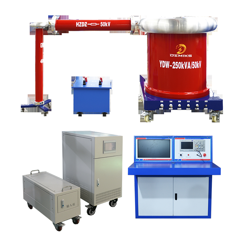
Partial Discharge Test System
-
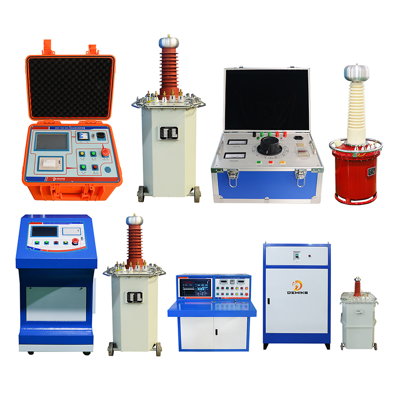
AC/DC Withstanding Voltage Tester
-
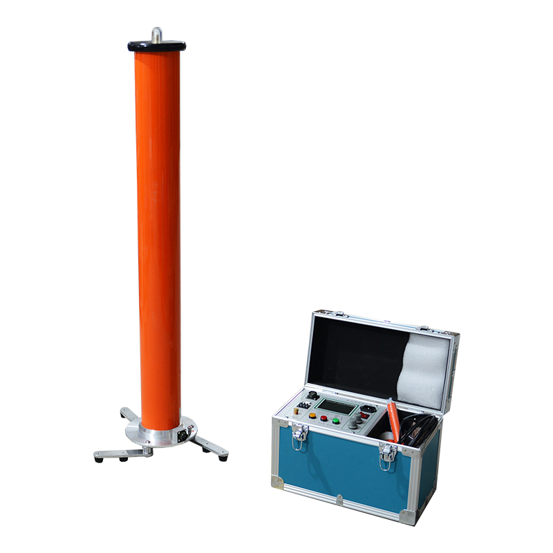
Variable Frequency Resonance Test System
-
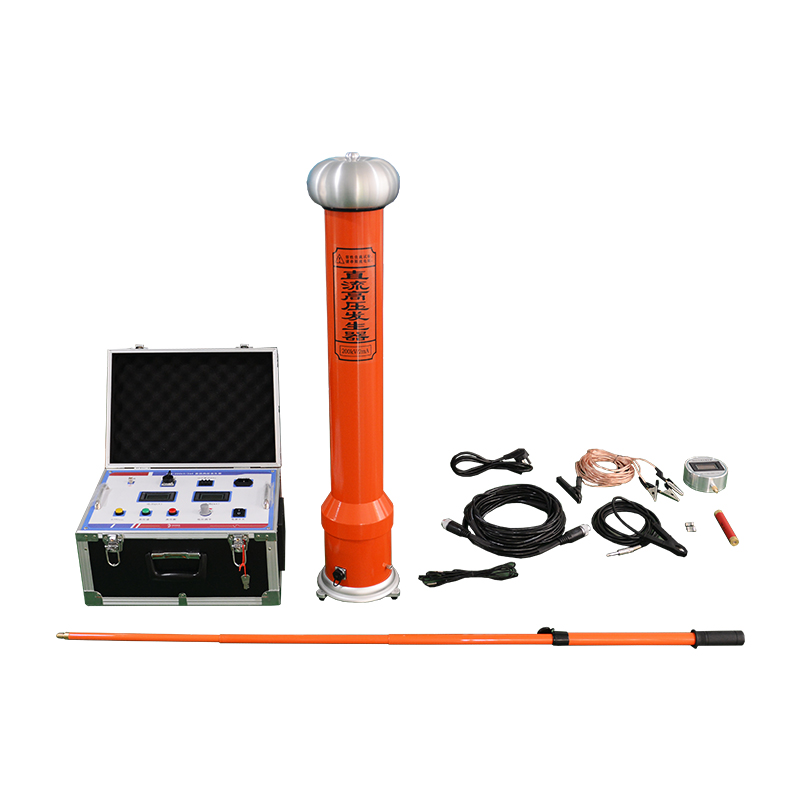
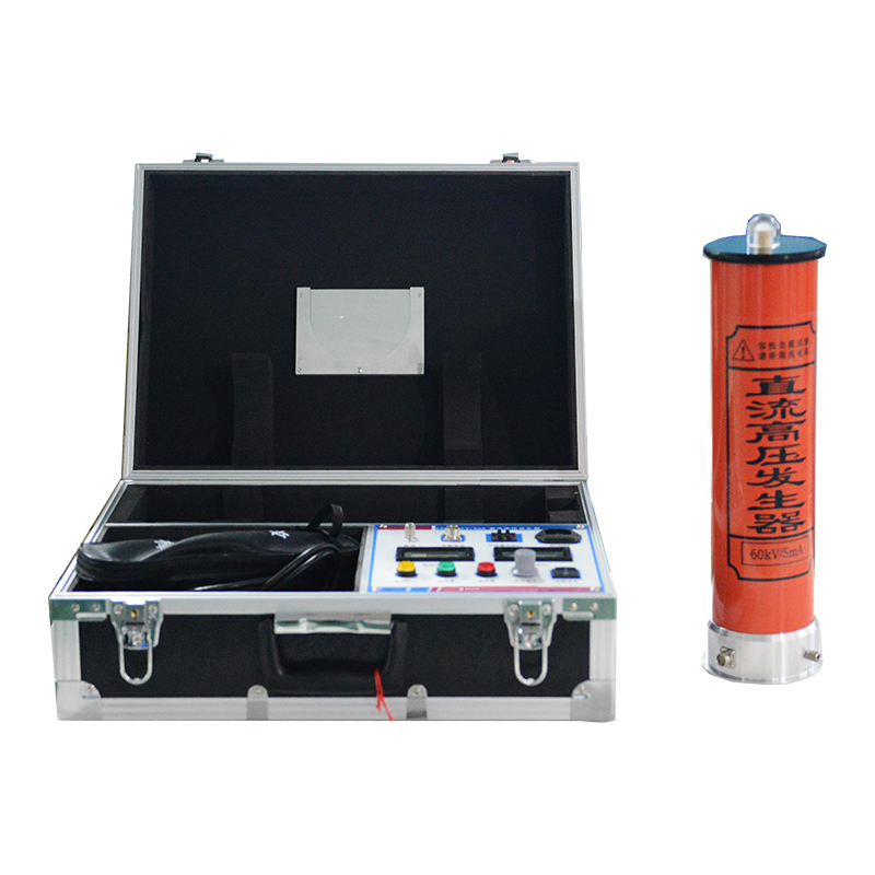
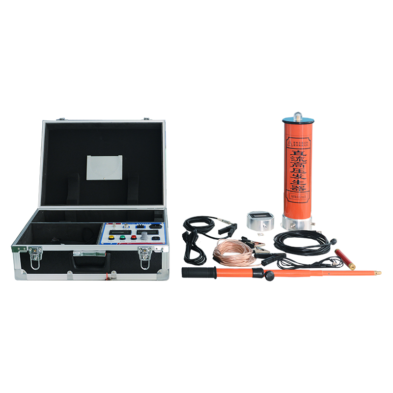
ZGF-300kV10mA DC High Voltage Tester
-
ZGF-200kV2mA DC High Voltage Tester
-
ZGF-120kV5mA Automatic DC High Voltage T
-
ZGF-60kV2mA DC High Voltage Tester
-
ZGF-60kV2mA DC High Voltage Tester
-
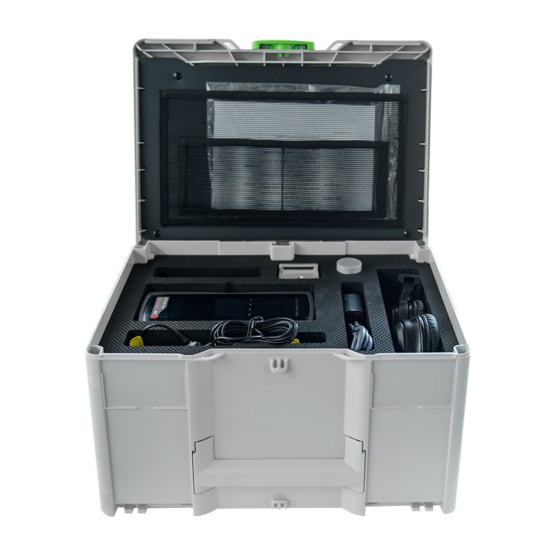
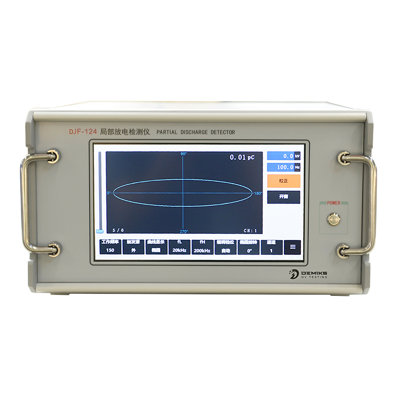
DJF-SC129 Local discharge detector
-
DJF-124 - Partial Discharge Detector