
Detailed procedure for current transformer accuracy testing
1. Test Objectives
Transformer tester manufacturer demiks specialised technicians point out that it is important to verify that the ratio error is within the specified class (e.g. 0.2%, 0.5%, 5P).
Measure phase angle error (critical for metering/protection)
Verify correct polarity
Check load capacity
Detect winding defects or core saturation
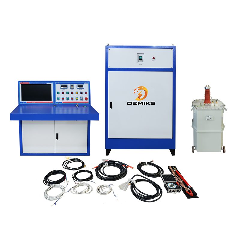
Transformer tester
2. Equipment Required
| Device | Purpose | Example Models |
|---|---|---|
| CT Analyzer | Ratio, excitation, burden tests | Omicron CTA 5X, Megger TTR-5 |
| Primary Injection Set | High-current testing | CPC 100, Doble F6150 |
| Burden Box | Simulate real load | Programmable RLC load |
| Phase Angle Meter | Measure phase displacement | Fluke 435, Zera LMG |
3. Step-by-Step Test Procedure
A) Visual Inspection
Check nameplate data (ratio, class, VA rating)
Verify physical condition (oil leaks, cracks)
Ensure secondary terminals are accessible
B) Insulation Resistance Test
Test Voltage: 1kV DC for <1kV CTs, 5kV DC for >1kV CTs
Minimum Values:
New CTs: >1,000 MΩ
In-service: >100 MΩ
C) Turns Ratio Test
Connect CT analyzer to secondary
Apply 50-100V AC to secondary
Measure induced primary voltage
Calculate ratio:
Actual Ratio=VsecondaryVprimaryCompare with nameplate ratio
Acceptance Criteria:
Metering CTs (Class 0.2, 0.5): ±0.1%
Protection CTs (Class 5P, 10P): ±1%
D) Polarity Test
Method 1: DC Kick
Connect DC source (+) to P1, (-) to P2
Momentarily touch S1 to (+) terminal of galvanometer
Observe needle deflection:
Positive kick = Correct polarity
Negative kick = Reversed
Method 2: Ratio Tester
Modern CT analyzers auto-detect polarity
E) Excitation (Saturation) Test
Leave primary open
Apply variable AC voltage to secondary
Record current vs. voltage (plot curve)
Key Parameters:
Knee-Point Voltage (Vk):
Where 10% V increase causes 50% I riseIEEE C57.13 Requirement:
Vk≥2×Isc×(RCT+Rburden)
F) Burden Test
Connect rated burden (e.g., 15 VA)
Inject 100% rated current (e.g., 5A)
Measure secondary voltage:
Burden=I2×Z
Acceptance:
Secondary voltage drop <2% of rated
G) Phase Angle Test
Critical for revenue metering
Use CT analyzer to measure displacement
Class 0.2 CT: Max ±10 minutes error
4. Accuracy Classes & Tolerances
| Class | Ratio Error | Phase Error | Application |
|---|---|---|---|
| 0.1 | ±0.1% | ±5' | Precision labs |
| 0.2S | ±0.2% | ±10' | Revenue metering |
| 0.5 | ±0.5% | ±30' | Industrial metering |
| 5P | ±1% | ±60' | Overcurrent protection |
| TPX | ±0.5% | ±30' | Bus differential |
5. Common CT Faults Detected
| Test | Fault Indicated | Diagnostic Action |
|---|---|---|
| High ratio error | Shorted turns | Perform DGA (oil CTs) |
| Low excitation | Open winding | Check secondary circuit |
| Abnormal V-I curve | Core damage | Replace CT |
| High IR loss | Moisture ingress | Dry or replace |
6. Safety Precautions
✔ Always short-circuit CT secondary before disconnecting
✔ Use PPE during primary injection (>100A)
✔ Never open-circuit energized CT secondary (risk of kV-level voltages)
7. Test Report Template
markdown复制
CT ID: _______________
Date: _______________
Ratio Test:
- Measured: ______:1
- Nameplate: ______:1
- Error: ______%

Excitation Test:
- Knee-point: ______ V
- Magnetizing current @ Vk: ______ mA

Polarity: Correct/Incorrect
Insulation: ______ MΩ @ ______ V DC

Conclusion: Pass/Fail (Per IEC 61869-2)
Pro Tip: For protection CTs (Class PX, TPX), always compare excitation curves with factory data – even perfect ratio tests can mask saturation issues during faults.
Would you like specific procedures for testing optical CTs (non-conventional instruments transformers)?
The above content is published by demiks, please specify, demiks is a substation equipment manufacturer, specializing in the production of high-voltage tester, transformer tester, circuit breaker test equipment, relay tester, SF6 gas analyser, cable fault tester and other products, if you have power test testing needs, please feel free to contact demiks power science and technology limited company or send an email! Give us: contact@demikspower.com
 Relay Protection Testing and Commissioning Gu
 how to test microwave transformer
 how to reset circuit breaker with test button
 high voltage cable testing standards